Alpakka 1
OverviewManualGalleryComponents
Alpakka manual
DIY & Hardware
Setup
References
Profiles
Developer
Assembly
Some of the pictures below are from older controllers, but the process is fundamentally the same.
Materials and tools
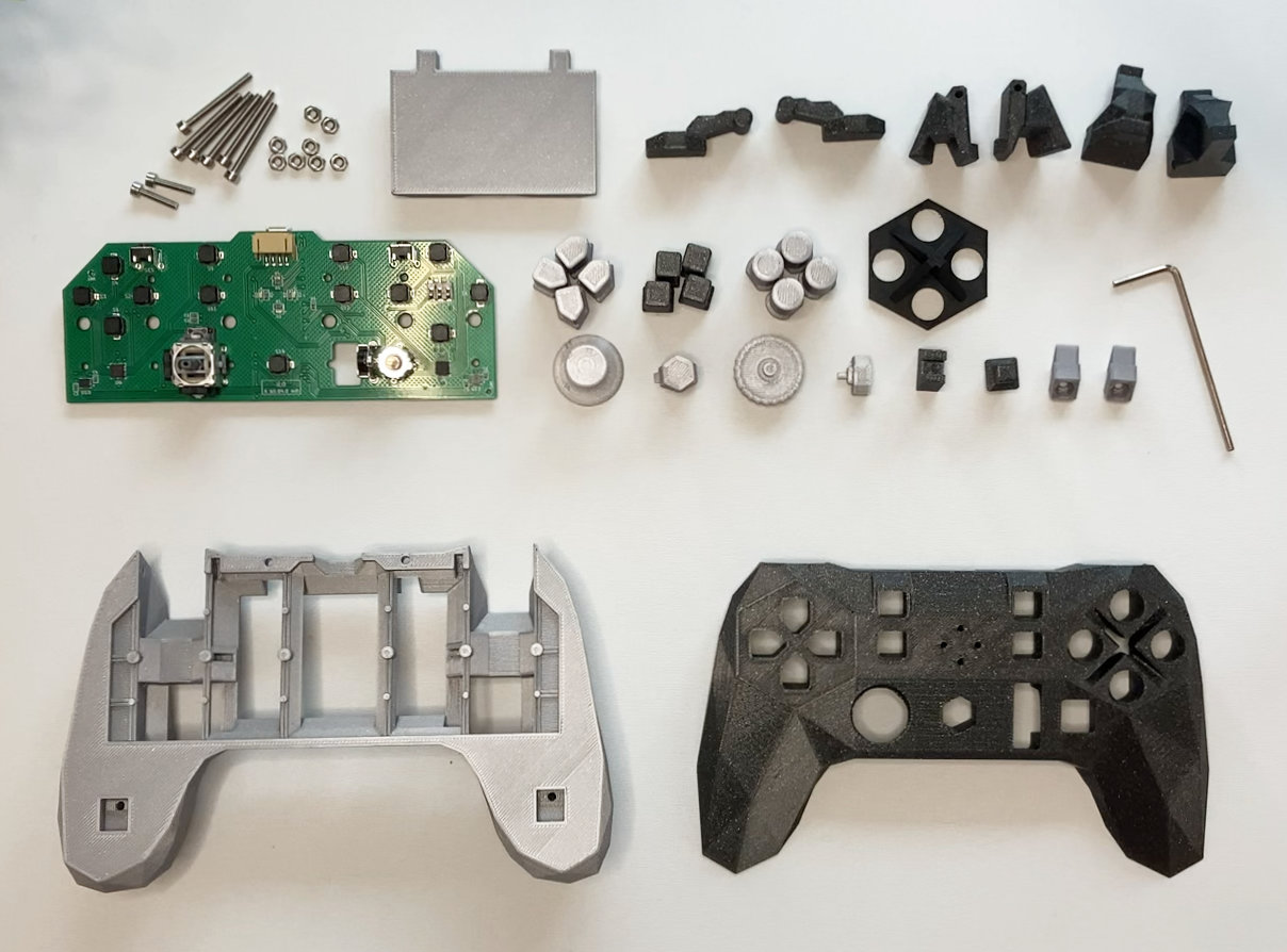
Materials
- PCB with all components soldered.
- All the 3D printed parts.
- M2.5 DIN-912 Hex-socket 12 mm bolts. (2x)
- M2.5 DIN-912 Hex-socket 25 mm bolts. (6x)
- M2.5 DIN-934 Hex nuts. (8x)
- (Optional) LiPo battery 503562.
Tools
- Hex key 2 mm.
Fit L2/R2 triggers
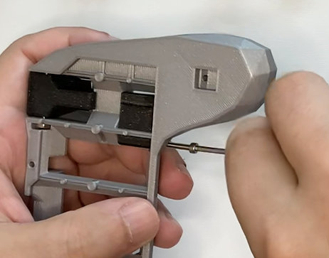
The L2 and R2 triggers are kept in place with a bolt (25mm) and nut, and pivot over it.
- Be sure that the bolt moves without restrictions through the trigger hole, otherwise put the bolt in and out several times until it does.
- Put the nut in the slot.
- Place the trigger in place (does not matter which side since the trigger is symmetrical).
- Put the bolt from the side, through the case and the trigger.
- Screw the bolt until it grabs the nut (do not screw it too tight).
- Check that the trigger mechanism moves freely when operated.
- Repeat in the other side.
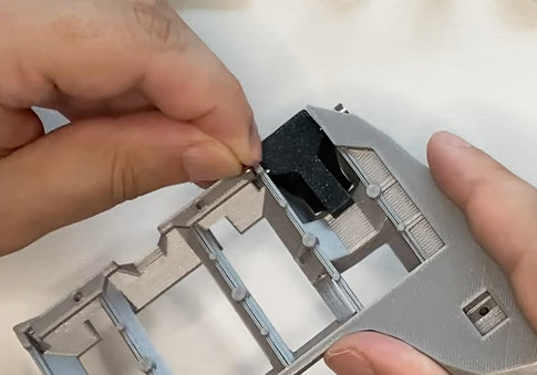
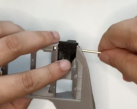
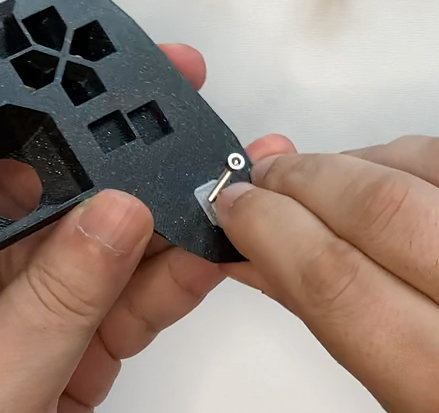
Fit L4/R4 triggers
The L4 and R4 triggers are kept in place with a bolt (25mm) and nut, and pivot over it.
- Be sure that the bolt moves without restrictions through the trigger piece, otherwise put the bolt in and out several times until it does.
- Place the trigger in place by tilting it (left and right pieces are different).
- Put the bolt from the bottom, through the case and the trigger.
- Put the nut in the slot.
- Screw the bolt until it grabs the nut (do not screw it too tight).
- Check that the trigger mechanism moves freely when operated.
- Repeat in the other side.
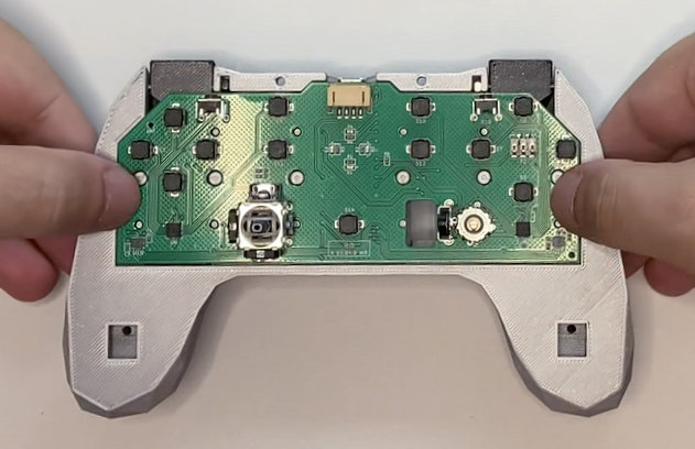
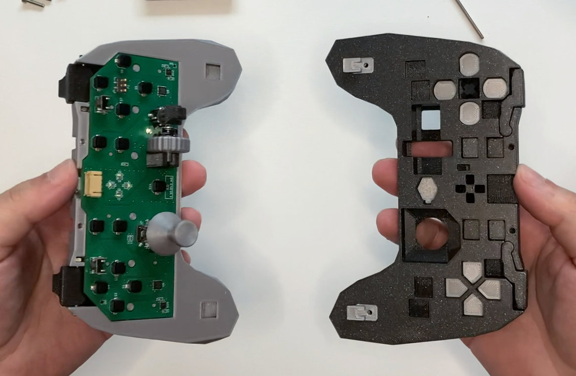
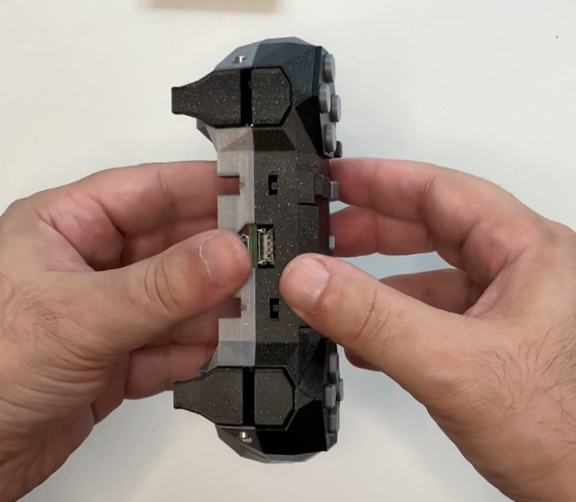
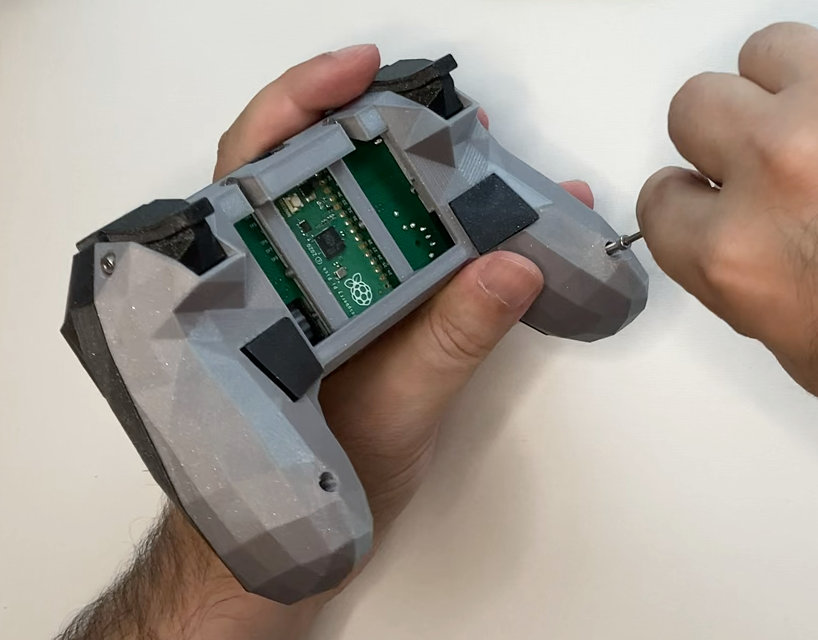
Assemble electronics
The PCB is kept in place thanks to the multiple mounting holes that the back case pillars are fitting. The first time a PCB is mounted it could be difficult to fit, so apply force carefully.
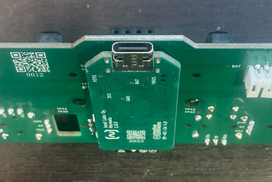
- Plug the Marmota code module into the main PCB.
- Put PCB on the case, aligning the case columns with the holes.
- Apply force carefully until it snaps in.
- Check that the surface of PCB sits flat, and at the same height than the case around it.
Fit thumbstick caps
The thumbstick cap fits into the thumbstick shaft just by pressure.
- Put the cap in place.
- Press down until it snaps in.
- Repeat with both thumbstick caps.
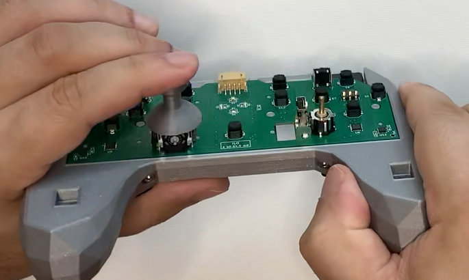
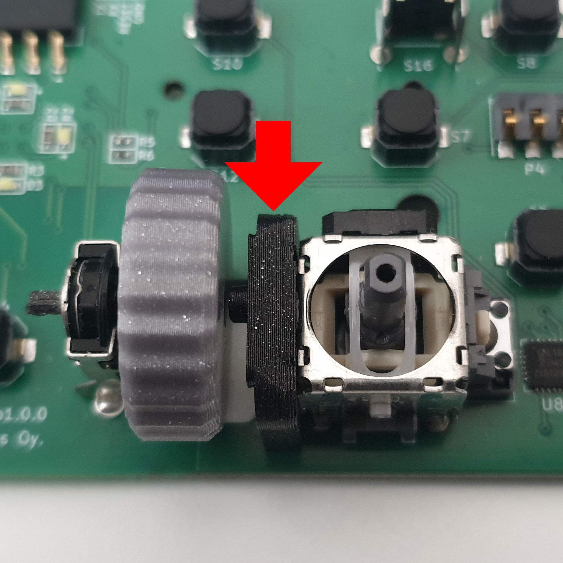
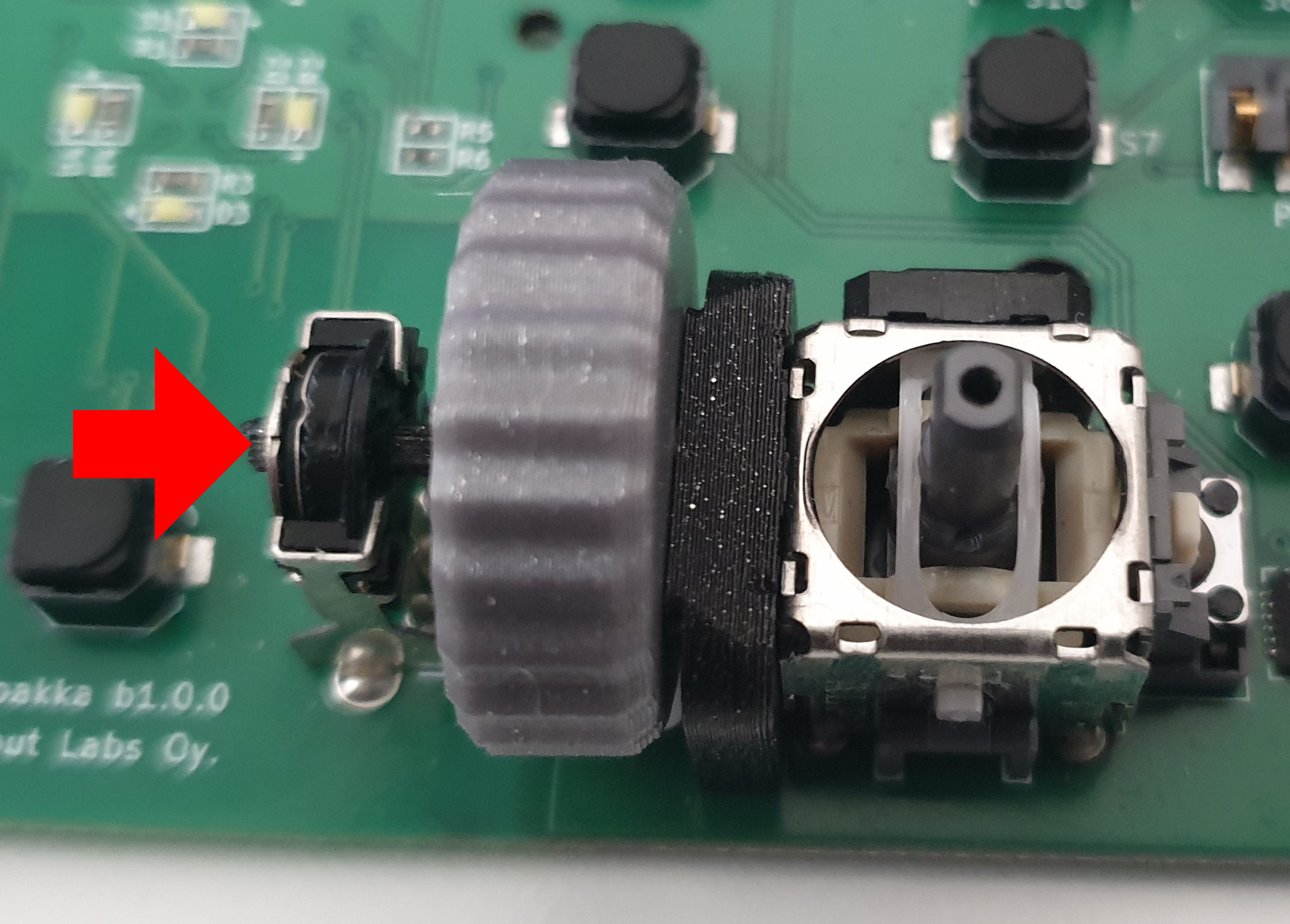
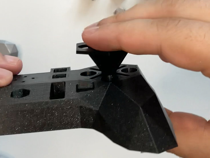
Assemble and fit scroll wheel
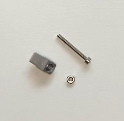
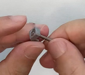
The scroll wheel is composed by the wheel, the core, and the support.
Before assembly: Check that the core can be inserted in the wheel with reasonable force (without requiring tools) but stays on it firmly.
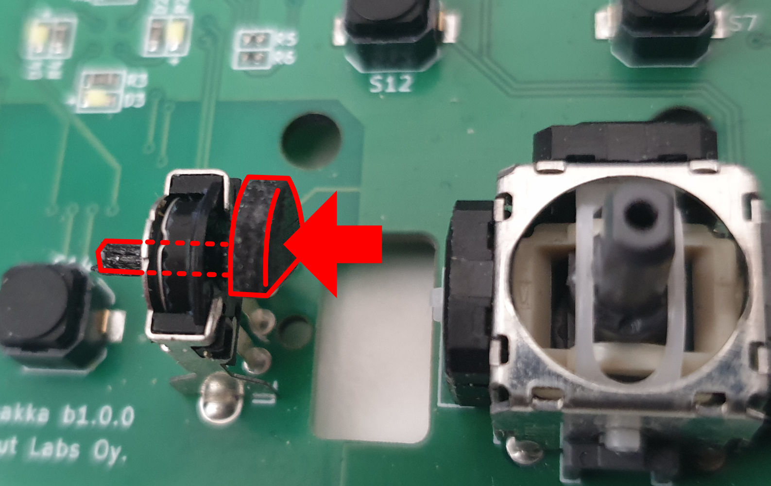
- Insert the core (only the core) into the encoder.
- Align the wheel with the core.
- Push the wheel all the way to the left, until the core is fully inserted and flat.
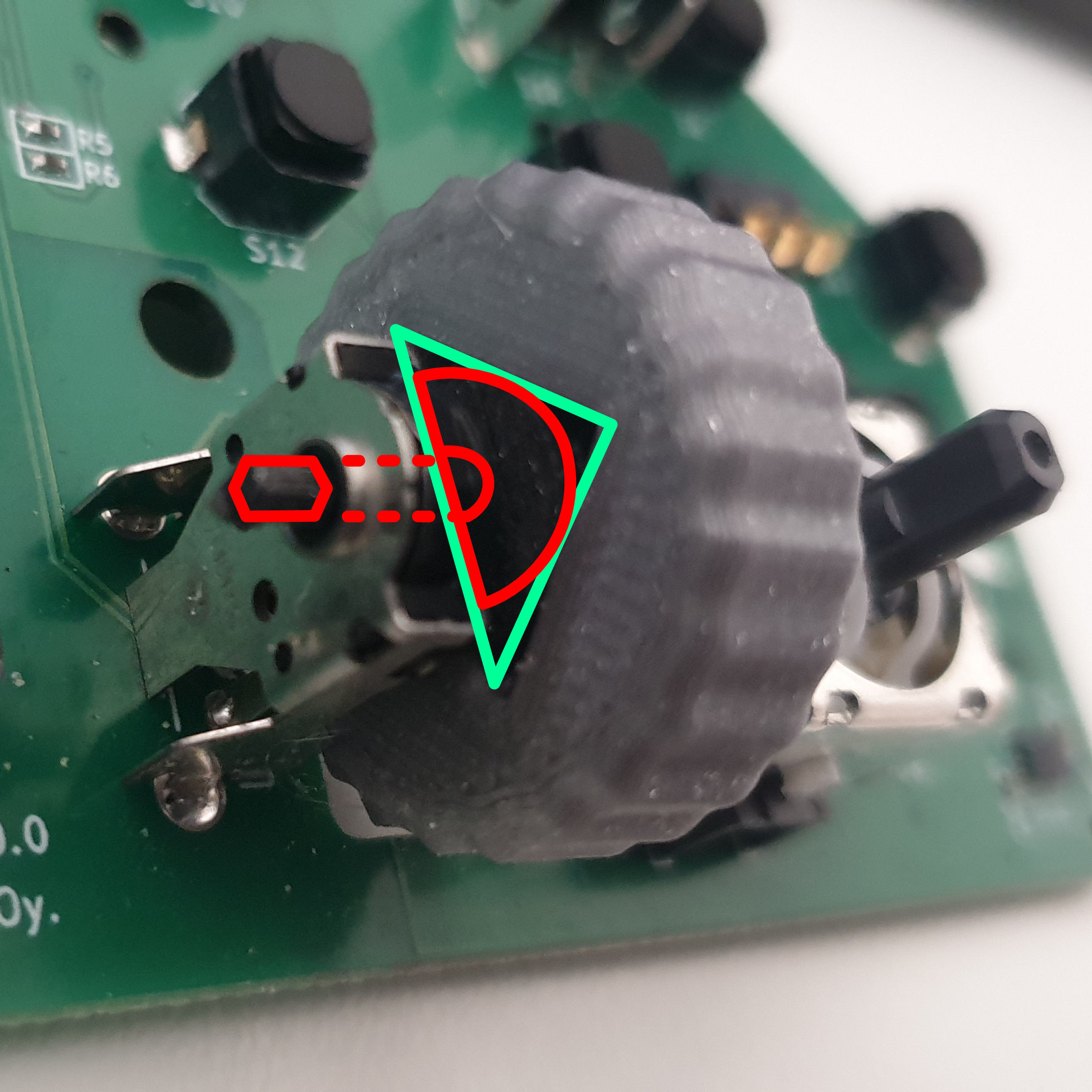
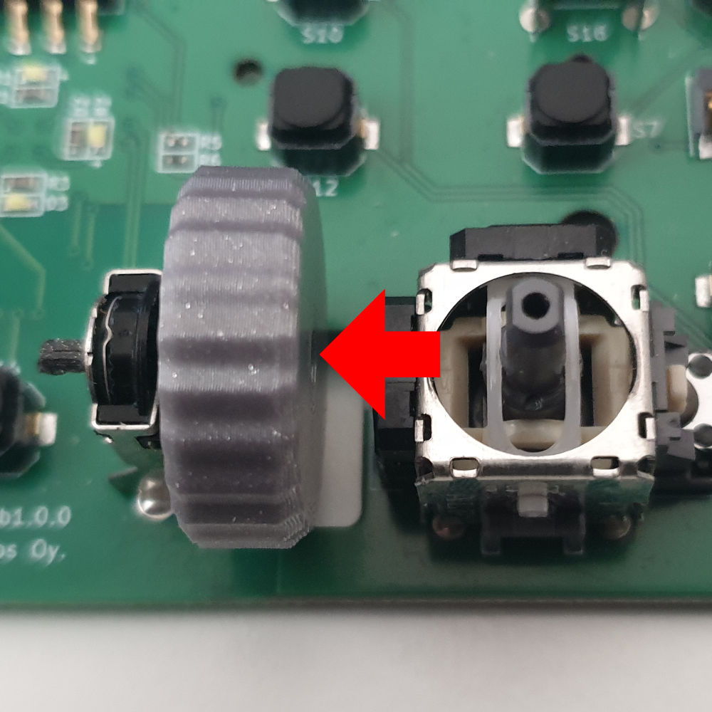
- Place the holder into into position (resting on the thumbstick side).
- Move the wheel-core assembly to the right by pushing the core shaft from the other side of the encoder.
- Check that the wheel rotates freely and it is correctly aligned / does not wobble.
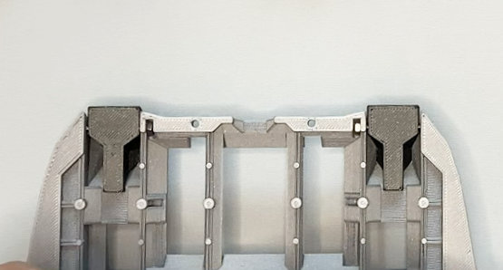
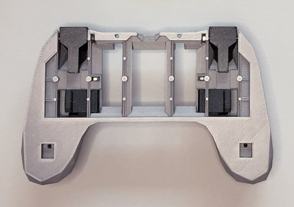
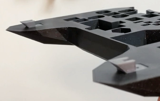
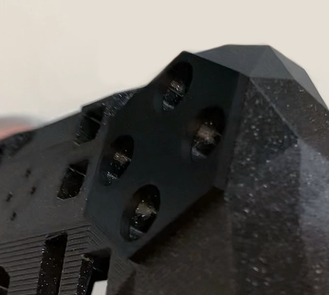
Assemble and fit anchors
The anchors serve a double purpose of aligning the front and back cases while assembling them, and hosting the hex nuts internally.
- Take an anchor piece and put the nut into the nut slot.
- Introduce a bolt from the other side so it holds both the anchor and the nut.
- Fit the anchor into the front case by pressure, until it sits flat.
- Remove the bolt.
- Repeat in the other side.
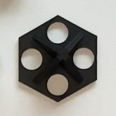
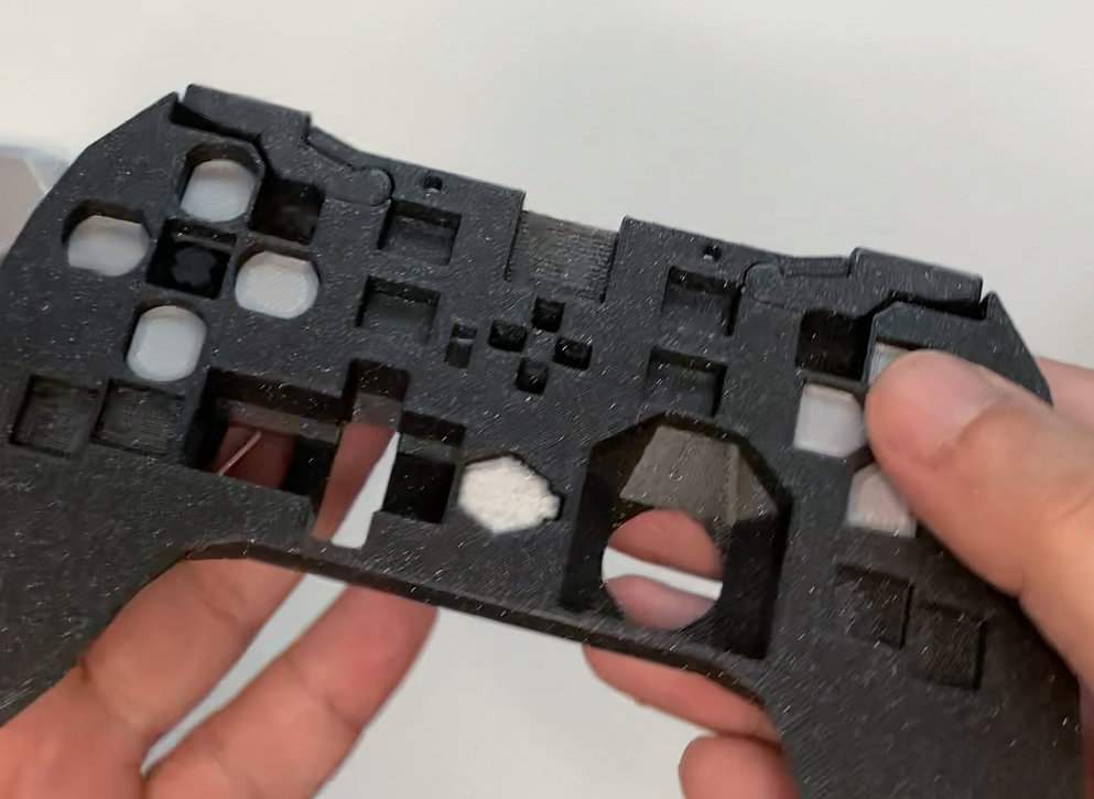
Fit conductive hexagon
The hexagon behaves as a touch sensitive surface and it is held in place by pressure.
- Align the hexagon over the front case (be aware there are 2 correct and 2 incorrect orientations).
- Apply pressure until the piece snaps in.
- Check that there is no gap between the hexagon and the case.
Place buttons
It's time to play shapes and holes, also the cow goes moo.
- Put the front case upside down.
- Place ABXY, Dpad, Select, Home, and shoulder buttons in their slots.
- Check that all the buttons move freely when pushed from the other side.
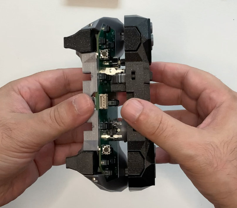
Tactical Sandwich Maneuver
Both front and back cases are now ready to be put together.
- Take both front and back cases, facing up.
- Move them both vertically, do not flip the front case or the buttons will fall.
- Align the anchors on the bottom, so they attach first.
- Join the cases together, move the thumbstick cap a bit if needed.
- Keep holding them for the next step.
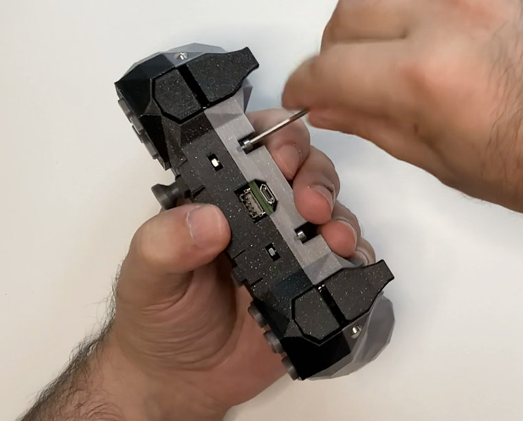
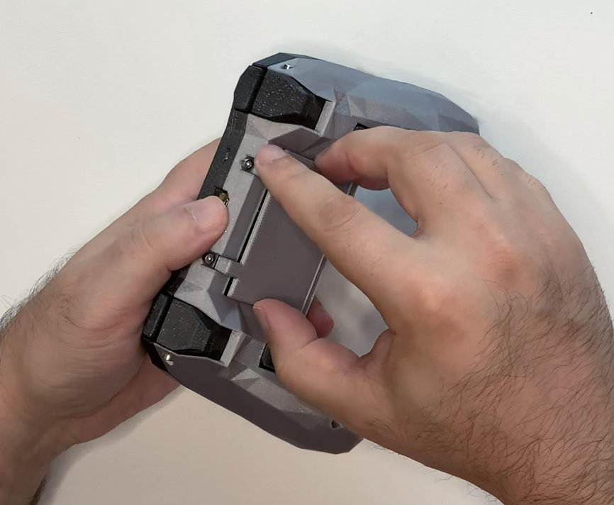
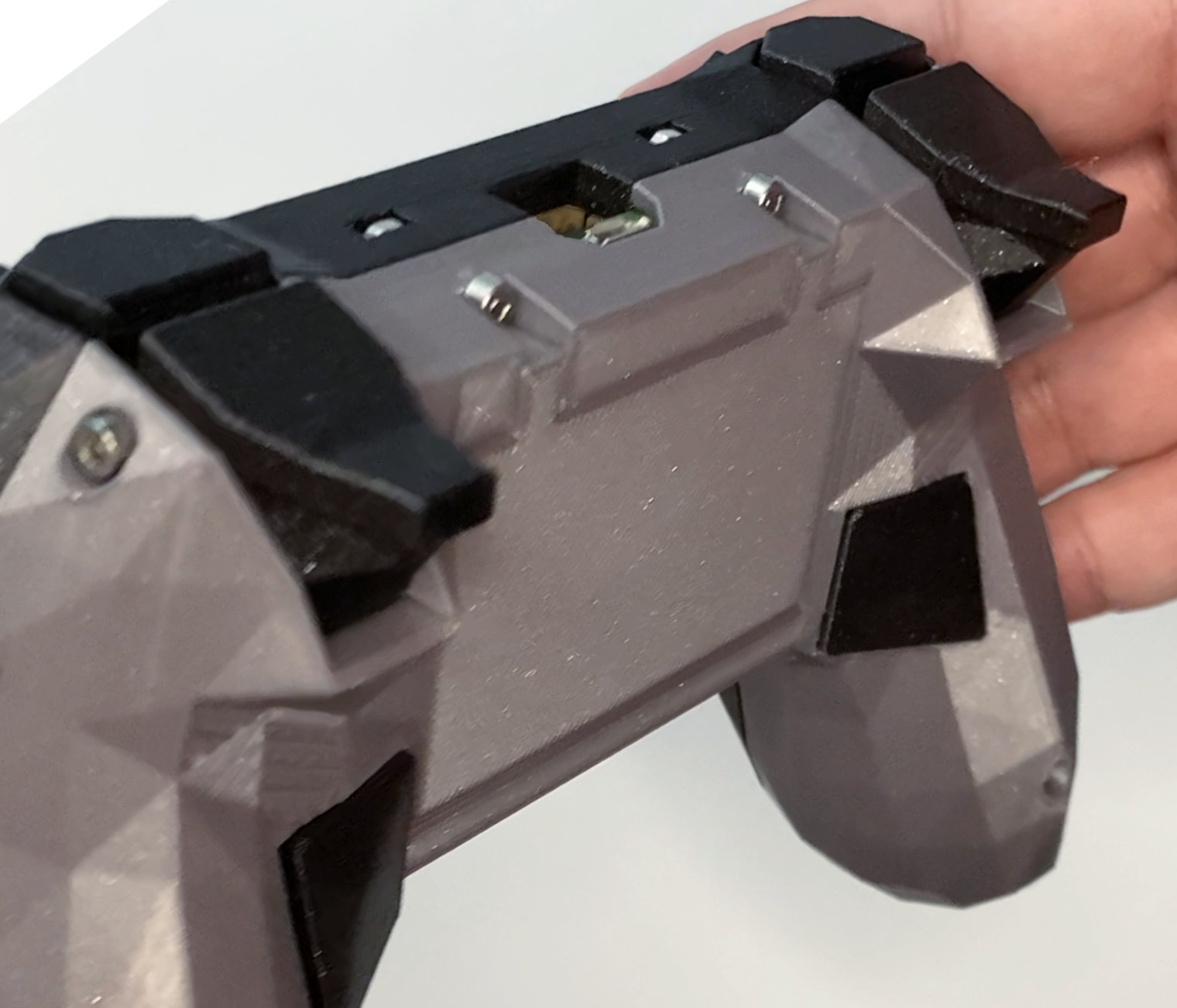
Screw case bolts
Bolts and nuts will hold the cases together, the top bolts are 12mm and the handle bolts are 25mm. The nuts on the handles are already secured inside the anchors.
- Put 2 hex nuts into the top nut slots.
- Screw in the 12mm bolts in the top.
- Screw in the 25mm bolts in the handles (do not screw these too tight or will force the anchors out).
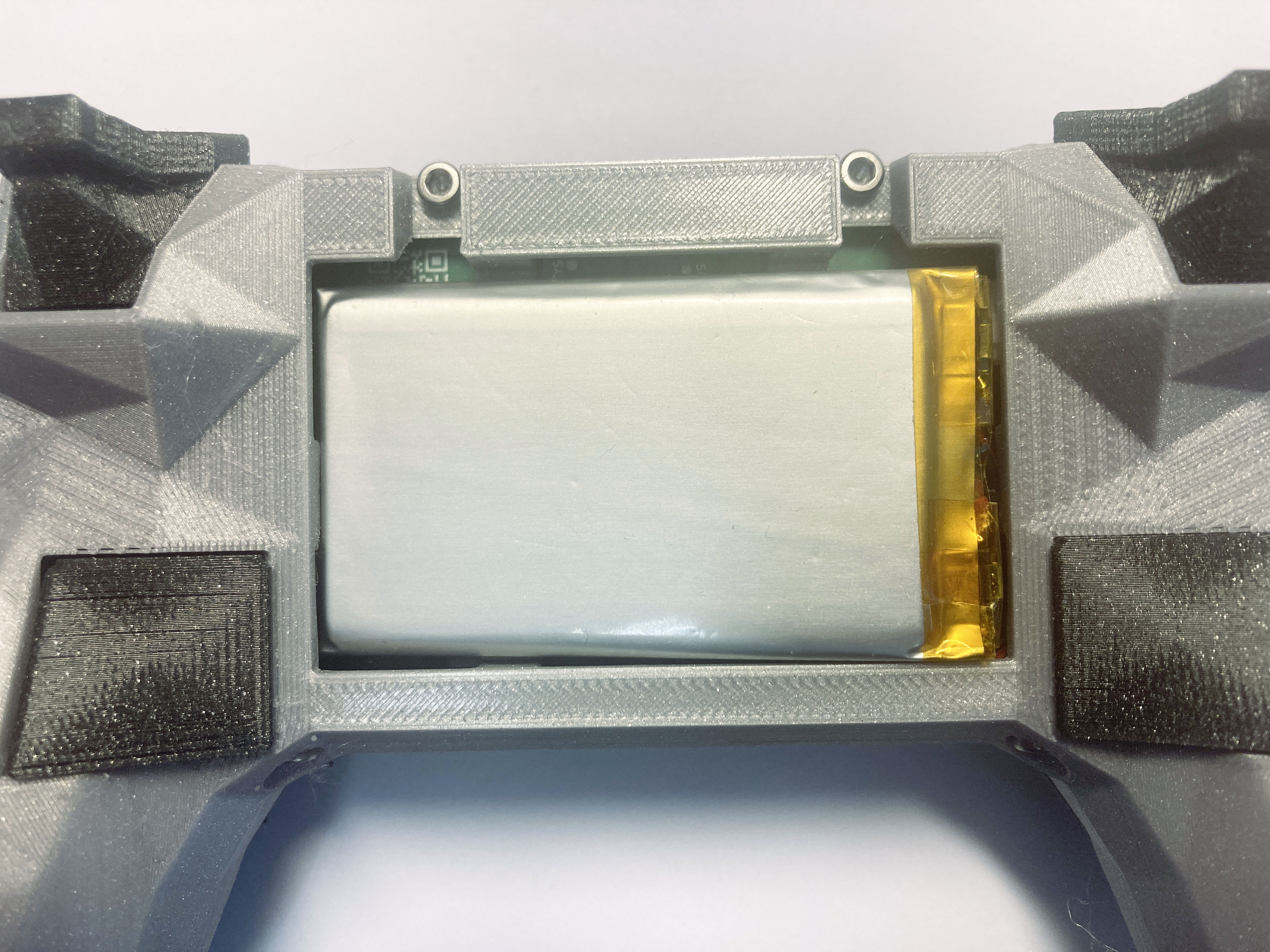
Place battery / cover
The rear bay cover fits by pressure. Guess what is that slot for! :)
- (Optional) Plug the battery connector.
- (Optional) Tuck the cable carefully in the clearance, in a way that does not push the battery out when placed.
- (Optional) Place the battery in position.
- Align the rear cover.
- Press until the cover snaps in (be careful not to pinch the battery edges).


Final adjustments
Check that all the buttons move freely and have a satisfying feedback.
Tight tolerances in 3D printing are hard!, so if some of the buttons are stuck or too tight (specially the triggers), do not discard them away yet! It is possible to use sandpaper on their contact surface (the internal flat part touching the switch) until they are a perfect fit. All the parts are designed with this workaround in mind.