Alpakka 1
OverviewManualGalleryComponents
Alpakka manual
DIY & Hardware
Setup
References
Profiles
Developer
Solder the Printed Circuit Board
Remaining components
Usually the manufacturing process only soldered some of the SMD components, so there are a few extra components to be soldered manually (trigger switches on the back, and through-hole components on the front), check which components you need in Components.
(Some of the pictures below are from older PCB versions, but the process is fundamentally the same).
Tools
Required:
- Soldering iron.
- Solder (~0.6mm recommended).
- Flux pen.
- Safety googles.
- Well ventilated room.
Optional:
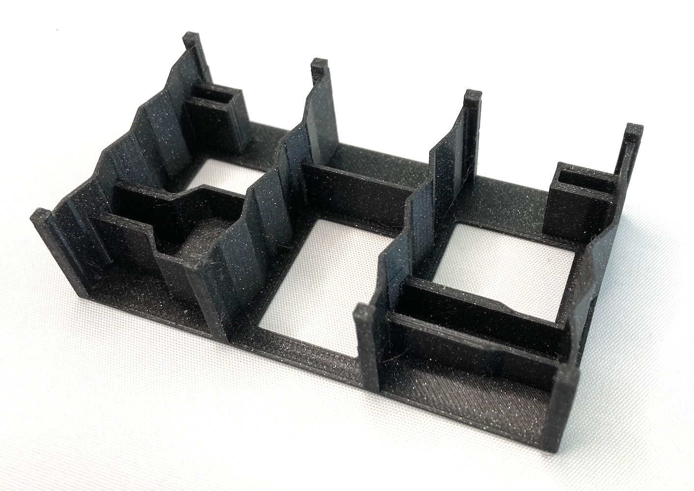
- 3D-printed PCB stand.
- Any kind of tape or stickers (to hold some components in place).
- Fan (to blow the smoke away from the face).
- Multimeter (for continuity tests).
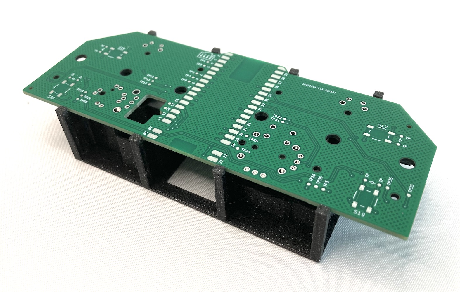
To make the soldering easier is possible to 3D-print a PCB stand, which allows to place the PCB upside-down, keeps the PCB flat, and the through-hole components in their correct positions.
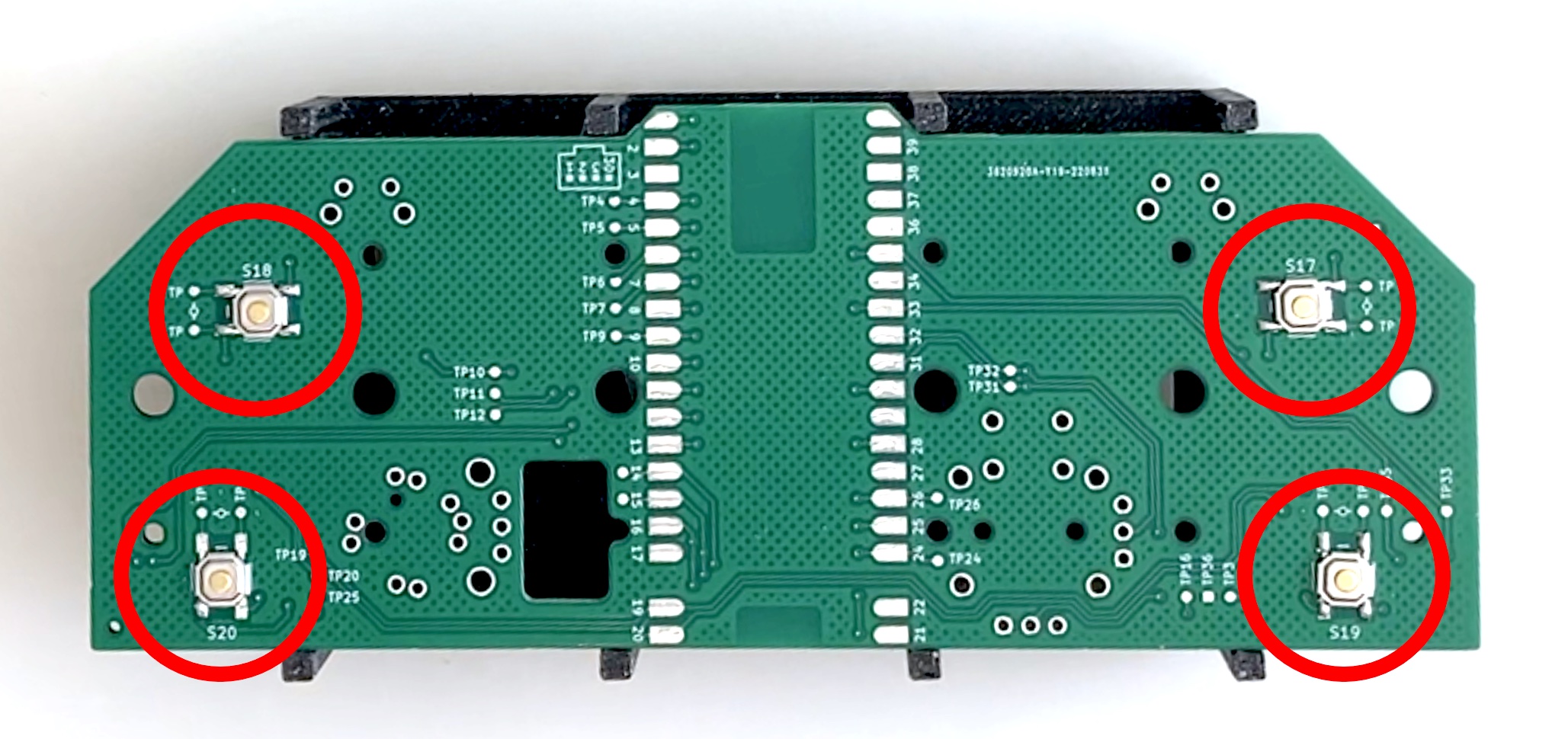
Solder back triggers buttons (L2, R2, L4, R4)
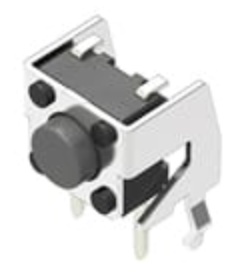
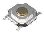
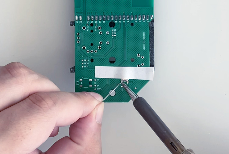
A total of 4 Alps Alpine SKQGAFE010 have to be soldered on the back of the PCB, these are SMD devices, but have long legs easy to solder with a normal soldering iron, and can be held in place with a piece of tape.
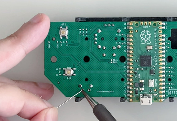
- Place the PCB on the stand.
- Apply flux pen to PCB pads.
- Place the button and hold it with a piece of tape.
- Solder first leg.
- Remove tape.
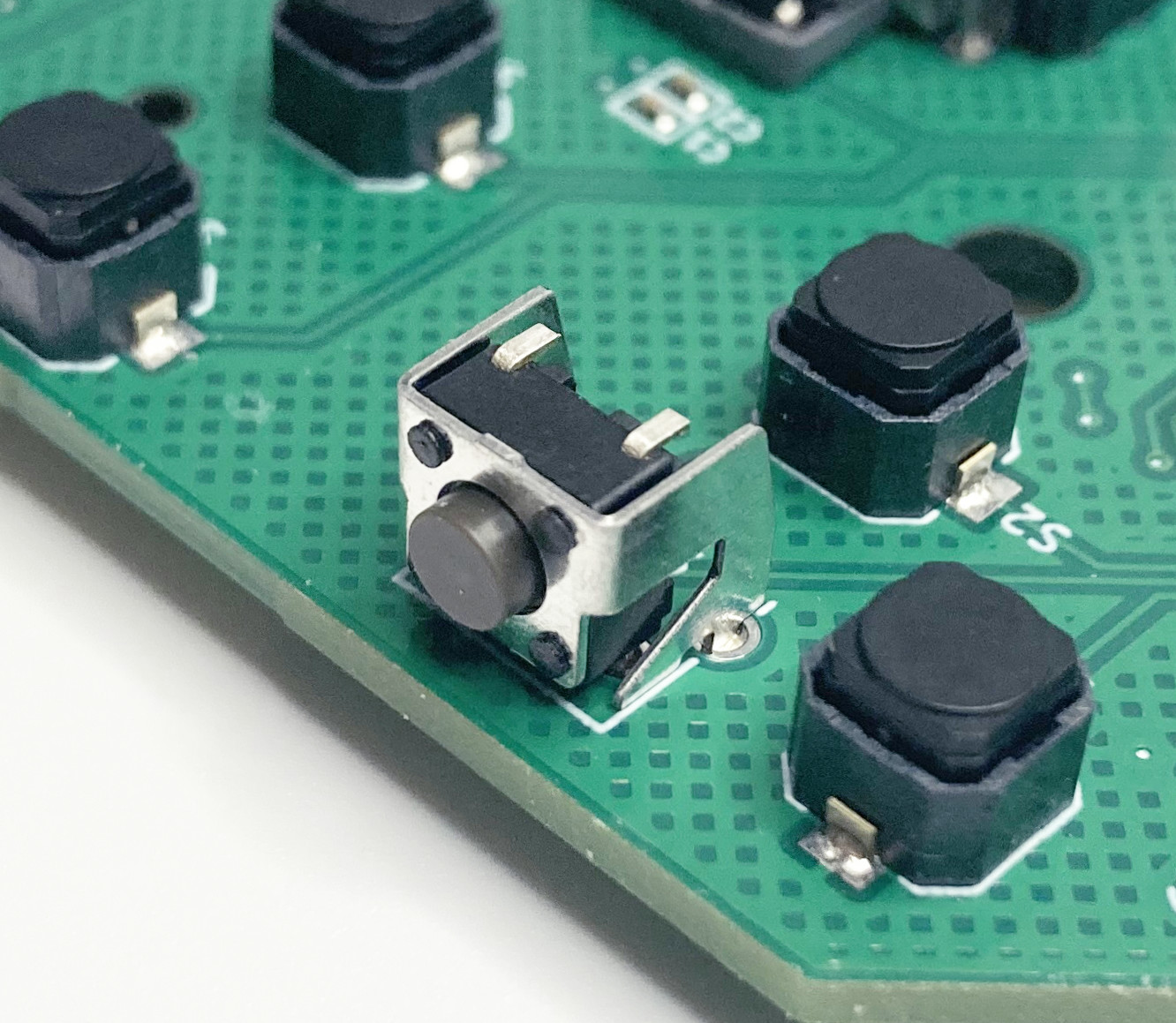
- Check that the button is correctly aligned and flat, otherwise resolder first leg.
- Solder the other 3 legs.
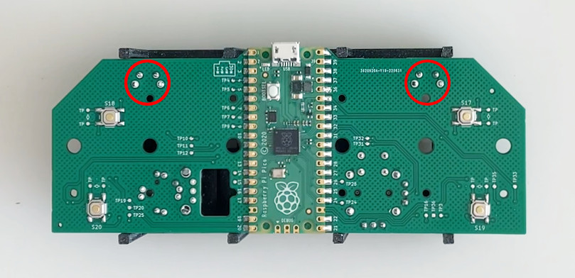
- Check continuity test points (TP) with the multimeter (while clicking the button).
- Repeat (4x).
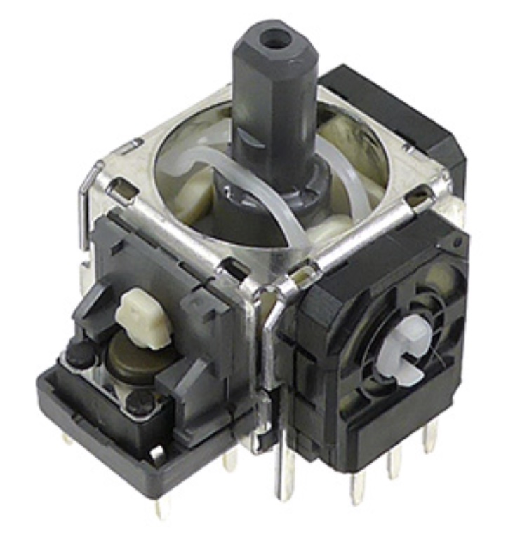
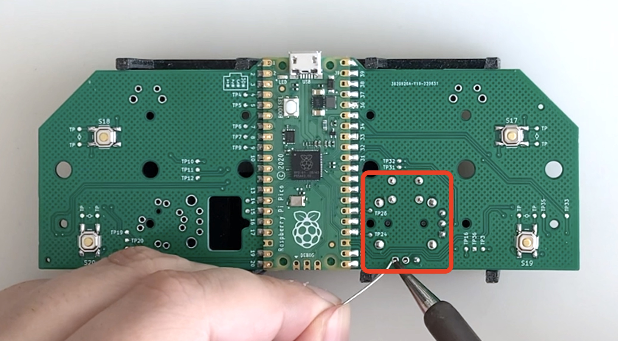
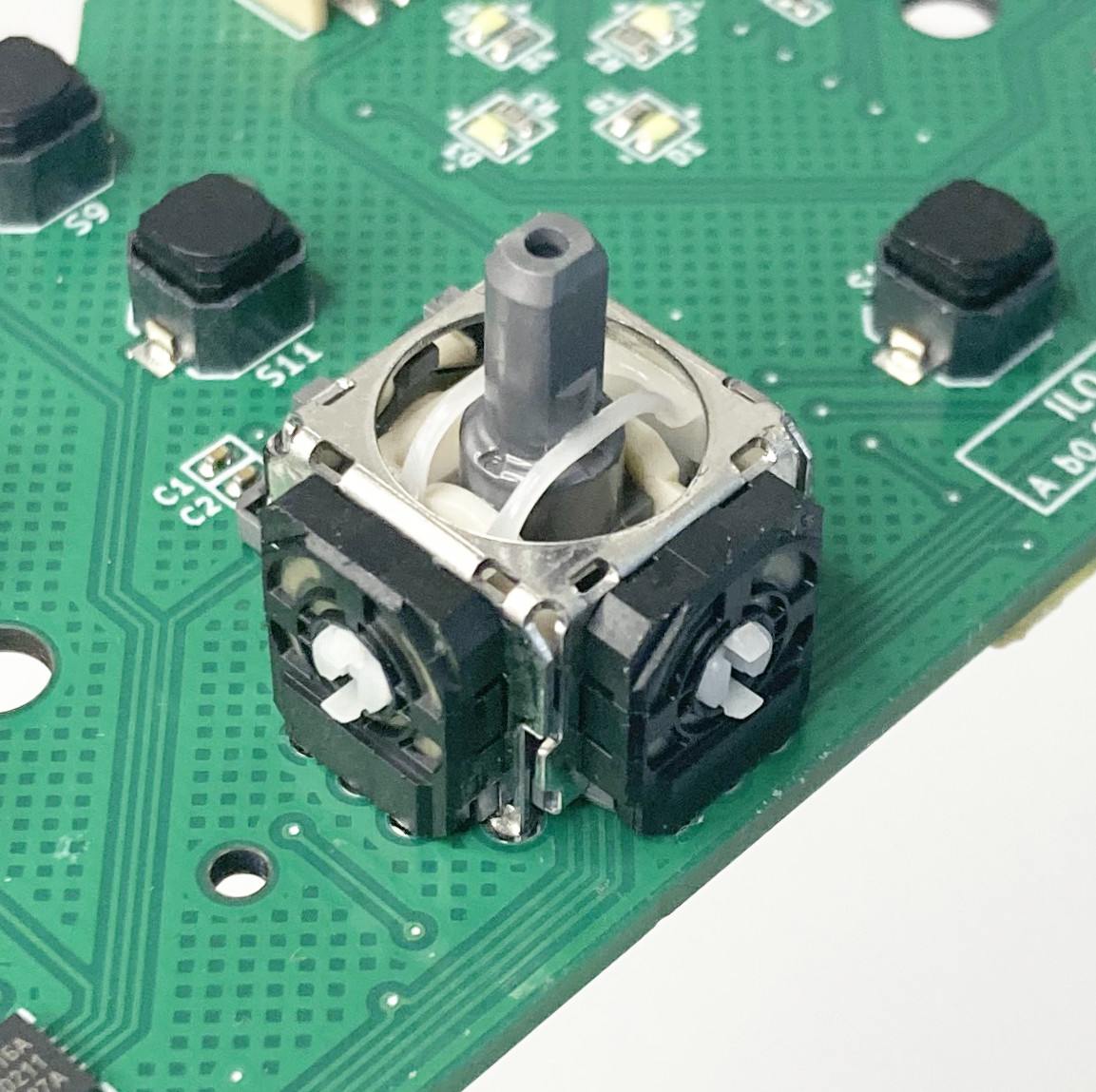
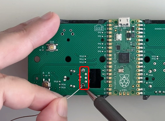
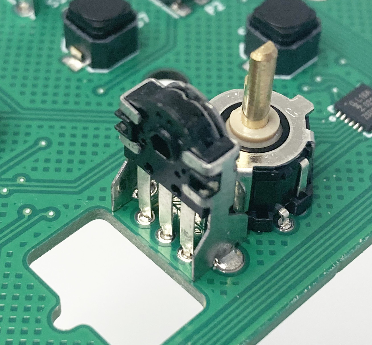
Solder thumbsticks
The Alps Alpine RKJXV122400R is held in place to be soldered thanks to the PCB stand. Be sure that the part is flat and there are no gaps before soldering all the pins.
- Apply flux pen to PCB holes.
- Place the thumbstick on the PCB (front side).
- Place the stand on the PCB (front side).
- Flip the stand+PCB block.
- Check that there is not gap between the thumbstick and the PCB.
- Solder just one pin.
- Check that the thumbstick position is flat, otherwise resolder first pin.
- Solder all the other pins.
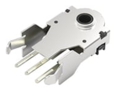
Solder rotary encoder (Scrollwheel)
The Alps Alpine EC10E1220503 should stay in place with its own snap-in legs, if that's not the case bend the legs outwards a bit until it does. Be sure that the part is flat and there are no gaps before soldering all the pins.
- Apply flux pen to PCB holes.
- Place the encoder on the PCB (front side), it should snap-in.
- Check that there is not gap between the encoder and the PCB.
- Place the PCB on the stand.
- Solder just one pin.
- Check that the encoder position is flat, otherwise resolder first pin.
- Solder all the other pins.
Solder shoulder trigger buttons (L1, R1)
The Alps Alpine SKHHLNA010 should stay in place with its own snap-in legs, if that's not the case bend the legs outwards a bit until it does. Be sure that the part is flat and there are no gaps before soldering all the pins.
- Apply flux pen to PCB holes.
- Place the button on the PCB (front side), it should snap-in.
- Check that there is not gap between the button and the PCB.
- Place the PCB on the stand.
- Solder just one pin.
- Check that the button position is flat, otherwise resolder first pin.
- Solder all the other pins.
- Repeat (2x).